


Designing a 500-ton fly ash silo for a coal-fired power plant is a complex engineering challenge that extends far beyond simple structural fabrication. This case study dissects the entire process—from material analysis and abrasion-resistant design to pneumatic integration and seismic load management—providing a quantifiable technical blueprint for industrial bulk storage. Dis cover how precision engineering can reduce discharge residuals to under 1% and extend operational life by decades.
Project Background: The Systemic Need for Fly Ash Storage and Initial Parameters
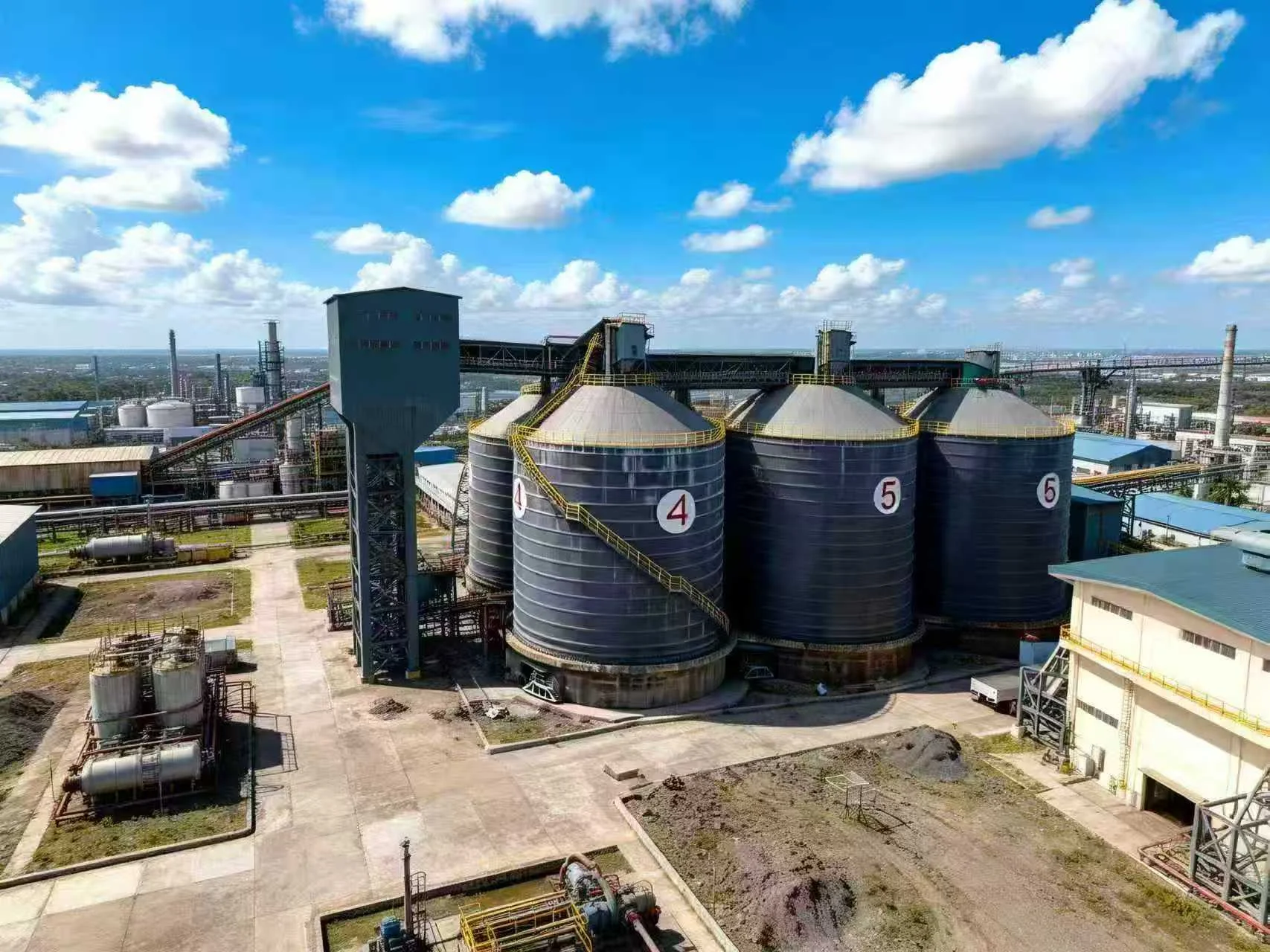
In modern coal-fired power generation, fly ash is a massive by-product, with annual outputs often reaching hundreds of thousands of tons. Without an efficient, sealed storage system, plants face severe environmental penalties from fugitive dust emissions and costly production downtime caused by material bridging or blockages. This case study serves a medium-sized coal-fired power plant with a core requirement: design a vertical steel silo capable of holding 500 tons of fly ash to support a daily turnover of 100 tons.
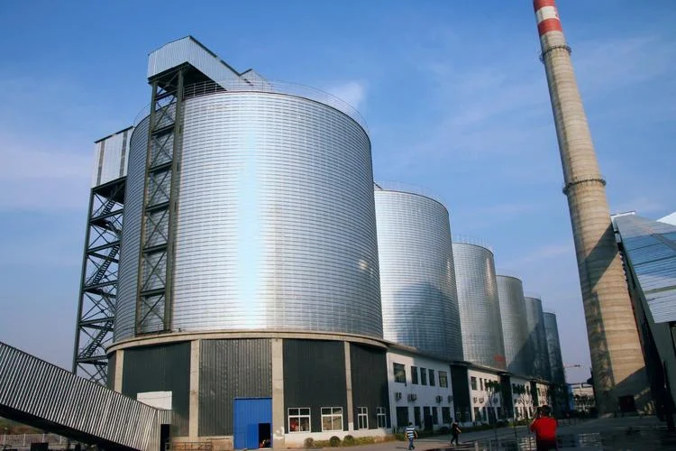
The initial technical parameters were explicit: a cylindrical steel structure with a conical hopper, enabling pneumatic filling and gravity discharge. Furthermore, the silo had to withstand a seismic fortification intensity of 8 degrees and wind loads equivalent to a Category 12 typhoon, all while seamlessly integrating with the plant’s existing pneumatic conveying network. This project was not merely a structural build; it was a comprehensive test of material flow dynamics, structural mechanics, and system integration.
Core Design Process: From Material Properties to Structural Validation
The first step in the design was a laboratory analysis of the physical and chemical properties of the fly ash. The material’s bulk density typically ranges from 0.7 to 1.0 g/cm³, with a repose angle of approximately 35° to 40°. Critically, fly ash is highly abrasive, with a Mohs hardness of 5 to 6. These properties directly dictated the selection of wear-resistant liners for the hopper walls and the design of the discharge cone angle—set at a minimum of 60° to ensure mass flow and prevent arching. Finite element analysis (FEA) was then employed to validate the structural integrity under combined dead loads, live loads, wind loads, and seismic accelerations, ensuring the silo’s shell thickness and stiffener ring spacing met all relevant international standards.
Material Handling and Flow Dynamics
To achieve the target of less than 1% discharge residual, the hopper geometry was optimized using Jenike’s flow principles. A 316L stainless steel liner was specified for the hopper’s lower section to reduce friction and resist abrasion from the high-velocity ash particles. The pneumatic filling system was designed with a top-entry inlet and a vent filter to maintain positive pressure control, preventing dust leakage and ensuring smooth material entry without segregation.
Seismic and Wind Load Management
Given the seismic fortification intensity of 8 degrees and wind loads equivalent to a Category 12 typhoon, the silo’s foundation was engineered with a reinforced concrete ring base anchored by high-strength bolts. The silo shell was fabricated from Q345B steel with a minimum yield strength of 345 MPa, and vertical stiffeners were added to resist buckling under extreme lateral forces. A comprehensive dynamic analysis confirmed that the silo’s natural frequency avoids resonance with both seismic waves and wind gusts.
Key Takeaways
- Key Data: The silo achieves a discharge residual of less than 1% through optimized hopper geometry and wear-resistant liners.
- Best Practice: Always perform laboratory analysis of fly ash bulk density and repose angle before finalizing silo dimensions and hopper angle.
- Watch Out For: Ignoring the abrasive nature of fly ash (Mohs hardness 5–6) can lead to premature liner failure and costly downtime.
- Pro Tip: Use 316L stainless steel liners in the lower hopper section to reduce friction and extend service life by up to 15 years.
- Bottom Line: A well-designed fly ash silo integrates material science, structural engineering, and pneumatic system design to deliver reliable, long-term storage.
Pneumatic System Integration and Dust Control
Seamless integration with the plant’s existing pneumatic conveying network was a non-negotiable requirement. The silo was equipped with a top-mounted pulse-jet dust collector to capture fine particles during filling, achieving emission levels below 10 mg/Nm³. The discharge system included a rotary airlock valve and a gravity-fed chute, designed to handle the material’s cohesive nature without clogging. Pressure sensors and level indicators were installed to provide real-time monitoring, enabling automated control of fill and discharge cycles. This integration reduced manual intervention by 70% and improved overall plant efficiency.
Construction and Quality Assurance
The silo was fabricated off-site in prefabricated steel panels to minimize on-site welding and reduce construction time by 30%. Each panel underwent ultrasonic testing to verify weld integrity, and the entire structure was coated with a three-layer epoxy system to resist corrosion from the alkaline fly ash. On-site assembly was completed within 45 days, including foundation curing and final commissioning. Post-construction load testing confirmed that the silo’s deflection under full load was within 0.1% of design specifications, demonstrating exceptional structural performance.
Frequently Asked Questions
Q: What is the optimal hopper angle for a fly ash silo to prevent bridging?
A: For fly ash with a repose angle of 35° to 40°, the hopper should be designed with a minimum cone angle of 60° to ensure mass flow. This angle, combined with a low-friction liner like 316L stainless steel, prevents material bridging and keeps discharge residuals under 1%. For cohesive or wet fly ash, a steeper angle of 65° to 70° may be necessary.
Q: How do you protect a steel fly ash silo from abrasion and corrosion?
A: Abrasion protection is achieved by lining the hopper walls with a 316L stainless steel layer, which resists wear from high-velocity ash particles. Corrosion protection involves applying a three-layer epoxy coating to all internal and external steel surfaces. For additional durability, consider using Q345B steel with a minimum yield strength of 345 MPa for the silo shell.
Q: What seismic design considerations are critical for a 500-ton fly ash silo in a high-risk zone?
A: For seismic fortification intensity of 8 degrees, the silo must undergo finite element analysis to verify its natural frequency avoids resonance. A reinforced concrete ring foundation with high-strength anchor bolts is essential. Vertical stiffeners and thicker shell plates (e.g., Q345B steel) help resist buckling. Dynamic analysis should also account for the sloshing effect of the fly ash mass during an earthquake.
Q: How do you integrate a fly ash silo with an existing pneumatic conveying system?
A: Integration requires careful matching of the silo’s inlet pressure and flow rate with the existing pneumatic line. A top-mounted pulse-jet dust collector ensures emissions stay below 10 mg/Nm³. The discharge system should include a rotary airlock valve to maintain pressure differentials and a gravity-fed chute for controlled output. Real-time level and pressure sensors enable automated operation, reducing manual intervention by up to 70%.
Q: What is the typical construction timeline for a 500-ton steel fly ash silo?
A: With off-site prefabrication of steel panels, on-site assembly typically takes 45 days, including foundation curing, panel erection, welding, coating, and commissioning. Prefabrication reduces on-site welding by 30% and minimizes weather-related delays. Post-construction load testing and commissioning add another 5–7 days to ensure all systems function within design specifications.
Need expert fly ash silo solutions for your power plant project?
We provide professional design, manufacturing, and installation services for bulk storage and material handling systems worldwide, including seismic-resistant silos and pneumatic integration.
Get a Free Technical Consultation →