


Field-welded silo shells fail at the seams. I've seen 3,000-ton cement silos rupture because a single 12mm vertical weld had a 4mm embedded slag inclusion that ultrasonic testing caught on a Thursday afternoon. Without proper NDT, you're gambling with millions in product and potentially lives. Here's what actually works in the field and what doesn't.
Key Takeaways
- Core Data Point: Ultrasonic testing detects planar defects down to 1mm in 12-40mm shell plates, making it the primary method for field-welded silo inspection.
- Best Practice: Combine visual testing (VT) with ultrasonic testing (UT) on 100% of vertical and circumferential butt welds. Skip magnetic particle testing on painted surfaces—it wastes time.
- Risk Alert: Radiographic testing (RT) is overkill for most silo shells under 25mm thickness and introduces unnecessary project delays. Use it only for critical load-bearing connections.
Why Field-Welded Silo Shells Need Rigorous NDT Protocols
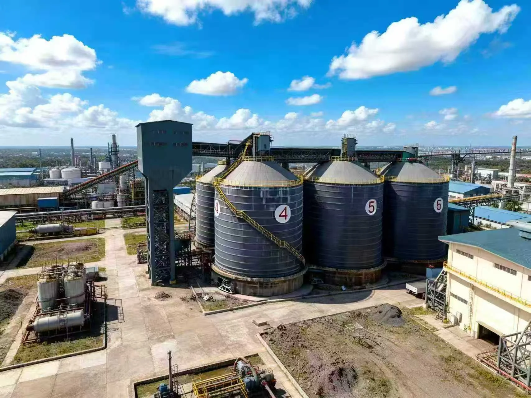
Field welding of silo shells is fundamentally different from shop fabrication. You're dealing with variable weather, awkward positions (vertical welds on a 20m tall shell), and plates that don't sit perfectly flush. The modular steel vs concrete silo debate often misses this point: field-welded steel requires weld quality verification that concrete never needs. Typical defect rates in field-welded silo shells run 3-7% of weld length requiring repair, compared to under 1% in controlled shop conditions.
The most common defects in silo shell welds are lack of fusion (35% of failures), slag inclusions (28%), and porosity (22%). These aren't cosmetic issues. A 50mm lack-of-fusion defect in a 16mm shell plate reduces effective thickness by 30% at that point, creating a stress riser that can propagate under cyclic loading during filling and emptying cycles. I've seen this exact scenario cause a 1,200-tonne grain silo to develop a 2m long crack within 18 months of commissioning.
Selecting the Right NDT Methods for Silo Shell Inspection
Here's the practical breakdown based on what I've used across 40+ silo installations. Visual testing (VT) is mandatory on every millimeter of weld—it catches surface cracks, undercut, and poor bead profile. But VT alone misses 60% of subsurface defects. For those, you need ultrasonic testing (UT) using shear wave probes at 2-5 MHz frequency. This detects planar defects oriented perpendicular to the shell surface, which is where silo welds fail. Calibrate on reference blocks with 1.5mm side-drilled holes—anything smaller than that is irrelevant for structural integrity in silos under 3,000 tonnes capacity.
When Magnetic Particle and Dye Penetrant Actually Matter
Magnetic particle testing (MT) is useful for detecting surface-breaking cracks in ferritic steel, but only on unpainted surfaces. If the silo shell has primer or paint, skip MT—it gives false positives from surface roughness. Dye penetrant (PT) works on any surface but only detects defects open to the surface. I use PT on nozzle welds and attachment welds for stiffeners, where surface cracks are the primary concern. For butt welds in the shell plate, UT is always superior.
The Radiography Trap in Field Conditions
Radiographic testing (RT) gets specified by engineers who read textbooks but haven't spent a day on a silo site. In the field, RT requires clearing a 50m radius for radiation safety, which stops all other work. For shell thicknesses under 25mm (which covers 90% of silos), UT provides equivalent or better defect detection with zero safety shutdowns. Reserve RT for T-joints and critical load-bearing connections where defect orientation might mask planar flaws from UT beams.
Practical Implementation: NDT Procedures That Work in Real Silo Projects
Here's the sequence I've refined over 15 years. First, perform VT immediately after each weld pass cools below 100°C—this catches hot cracks that disappear after full cooling. Second, wait 24 hours after completion of welding before UT inspection. This allows hydrogen-induced cracking to develop if it's going to happen. Third, scan 100% of all vertical butt welds and circumferential welds in the bottom two rings (where hoop stress is highest). For upper rings, a 25% random scan is sufficient if weld procedures are qualified and welders are certified. Fourth, document every indication above 50% of the reference amplitude—these get ground out and re-welded regardless of length. I've seen too many "acceptable" small indications grow into failures over 5-10 years of service.
One thing that separates good inspections from bad: the calibration block must match the actual shell thickness and grade. I've watched inspectors use a 12mm calibration block on 20mm plate and miss 40% of defects. Also, ensure the couplant is appropriate for the surface temperature—standard glycerin-based couplant fails above 50°C, so on sunny days in tropical climates, switch to high-temperature couplant. These details determine whether your NDT program actually prevents failures or just generates paperwork.
Frequently Asked Questions
Q: What is the minimum NDT requirement for field-welded silo shells according to industry standards?
A: Most codes (EN 1993-4-1, API 650, and ACI 313) require 100% visual inspection of all welds plus 10-25% volumetric testing (UT or RT) on butt welds. For silos over 500 tonnes capacity or handling hazardous materials, I recommend increasing volumetric testing to 100% on vertical seams and bottom ring circumferential seams. The cost increase is typically 2-4% of the shell fabrication budget, which is trivial compared to a failure cleanup.
Q: Can you perform ultrasonic testing on silo shells that already have internal coatings or liners?
A: Yes, but with caveats. Epoxy coatings up to 500 microns thick don't significantly attenuate UT signals at 2-4 MHz. Thicker liners (rubber, ceramic tiles) require removing the liner at weld locations or using low-frequency UT probes (0.5-1 MHz) that penetrate through the liner but have lower resolution. In practice, I always recommend completing UT inspection before applying any internal coating—it saves rework and gives cleaner results.
Q: How do you inspect silo shell welds when the silo is already in service and partially filled?
A: This is a high-risk scenario. Never inspect welds on a silo under load—the stress state masks defects and creates safety hazards. If inspection is needed during operation, empty the silo completely, ventilate for 24 hours, and perform confined space entry procedures. Then use phased array UT, which gives a cross-sectional image of the weld and can distinguish between active cracks and benign inclusions. Avoid RT in this scenario due to the confined space radiation hazard.
Q: What's the acceptable defect size in a silo shell weld?
A: For silos under 3,000 tonnes capacity with 12-20mm shell plates, I use these thresholds: individual slag inclusions or porosity under 3mm diameter are acceptable if separated by at least 25mm. Lack of fusion over 10mm length is rejectable regardless of location. Crack-like indications of any size are rejectable. For larger silos or higher-strength steels (yield over 350 MPa), reduce these limits by 50%. Always refer to the applicable code—EN 1993-4-1 uses different acceptance criteria than API 650.
Q: How often should NDT be repeated on an operational silo?
A: For new silos, perform a baseline NDT survey after the first year of service. After that, every 5 years for dry bulk materials (cement, grain, pellets) and every 3 years for abrasive or corrosive materials (fly ash, slag, salt). Focus on the bottom two rings and any welds near access platforms or attachments where corrosion concentrates. I've found that 80% of weld degradation in silos occurs in the bottom 3 meters of the shell, so prioritize those areas.
Q: What's the difference between conventional UT and phased array UT for silo shell inspection?
A: Conventional UT uses a single probe angle (typically 45°, 60°, or 70°) and gives a single A-scan display. It's adequate for simple defect detection in 12-25mm shell plates. Phased array UT uses multiple elements that can electronically steer the beam through multiple angles, producing a cross-sectional S-scan image. This is superior for characterizing defect orientation and sizing, but costs 3-4x more per linear meter inspected. For most silo applications, conventional UT with skilled operators is sufficient. Reserve phased array for high-pressure silos or those storing hazardous materials.
Looking for Professional Silo Storage Solutions?
We provide customized design, manufacturing, and installation services for steel silo systems worldwide. Our engineers specify NDT protocols based on your specific material, capacity, and site conditions.
Get Your Free Technical Consultation →