


Over 70% of unscheduled silo downtime originates from issues that daily visual inspections could have caught early. Yet many bulk handling facilities still rely on reactive maintenance, waiting for flow problems or structural alarms before taking action. This guide outlines a practical, engineer-tested daily inspection routine for steel silos handling cement, fly ash, clinker, and coal.Related: Power Plant Fly Ash Handling Optimization with Steel Silos
rong>Structural Integrity Checks: What to Look for Beyond Surface Rust
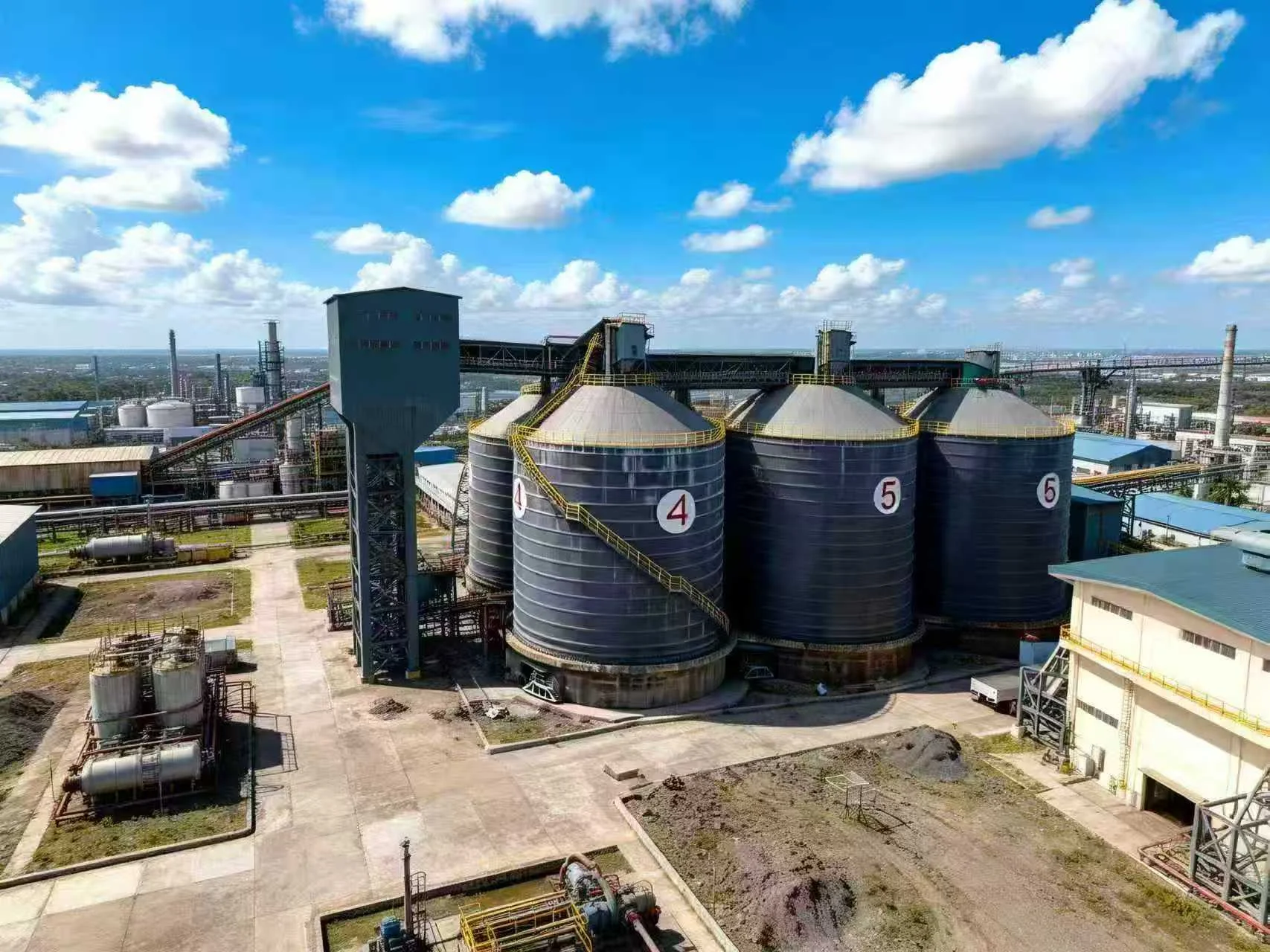
Start each inspection with a systematic walk-around, focusing on the silo shell, joints, and support structures. For bolted silos, pay close attention to the seam gaskets and bolt torque—loose fasteners are a leading indicator of fatigue in high-cycle loading environments. On spiral silos, inspect the interlocking seam for any visible gap or deformation, especially near the bottom ring where hoop stress is highest. A simple tool like a 0.10 mm feeler gauge can detect early seam separation that moisture and fines will exploit.
We recommend documenting any new dents, bulges, or coating failures with photos and a GPS-tagged location. Over a 12-month period, tracking these anomalies reveals patterns—for instance, consistent corrosion near the aeration inlet flanges suggests condensation from compressed air systems. For a deeper understanding of how structural design influences inspection priorities, review the engineering principles behind spiral steel silos and their structural advantages.
Aeration and Discharge System Verification for Cement and Fly Ash
Aeration systems are the most common source of flow disruptions in cement and fly ash silos. Daily inspection should verify that all aeration zones are active by checking pressure gauges at the manifold—a drop of more than 15% from baseline pressure indicates a blocked air pad or a leaking butterfly valve. For silos with fluidized discharge cones, listen for uneven air hissing, which signals that one quadrant of the cone is not fluidizing properly.
Air Pad and Nozzle Inspection Protocol
Inspect the aeration nozzles or pads through the clean-out ports. Look for material bridging or caked fines that restrict air flow. In fly ash applications, where moisture can cause hydration, we have seen a 30% reduction in discharge rate within 48 hours of a single failed air pad. For a complete technical breakdown of these systems, refer to the cement silo aeration systems technical guide for engineers.
Common Mistake: Ignoring the Vacuum Breaker
A clogged vacuum breaker is often overlooked during daily rounds. When it fails, the silo can collapse inward during rapid discharge or implode if the venting system is undersized. Test the breaker by manually lifting the valve—it should move freely and reseat without binding. In dusty environments, clean the seat weekly to prevent cement or fly ash from fusing to the sealing surface.
Key Takeaways
- Core Data Point: 70% of flow stoppages in cement silos originate from aeration system failures that daily checks can detect.
- Best Practice: Document every inspection with time-stamped photos and pressure readings to establish baseline trends.
- Risk Alert: A clogged vacuum breaker can cause catastrophic silo implosion—test it daily, not monthly.
Load Monitoring and Level Indicator Calibration on Coal and Clinker Silos
Load cells and level indicators drift over time due to thermal cycling, dust accumulation, and mechanical settling. For coal and clinker silos, where material density can vary by 15-20%, inaccurate level readings lead to either overfilling (structural risk) or underfilling (lost capacity). We recommend performing a daily zero-balance check on the load cells by comparing the tare weight against the known empty weight of the silo. A deviation greater than 2% warrants recalibration.
Ultrasonic and radar level transmitters should be cleaned of dust bridges every shift. In clinker applications, the abrasive dust can erode the sensor face within six months if not wiped down. For a more thorough understanding of how design affects load distribution, consult the cement silo load capacities technical guide. This knowledge helps inspectors interpret load cell readings in context with the silo's structural limits.
Environmental and Safety Checks for Bulk Material Storage
Daily inspections must extend to the silo's ancillary systems: dust collectors, pressure relief panels, and grounding cables. A dust collector with a torn bag allows fines to escape, creating a combustible dust hazard—especially in coal and fly ash storage. Check the differential pressure across the filter bags; a sudden drop signals a tear, while a steady rise indicates clogging. Pressure relief panels should be visually inspected for corrosion or debris that might prevent them from opening at the rated pressure (typically 0.5-1.0 psi).
Grounding continuity is non-negotiable for coal and fly ash silos. Use a multimeter to verify that the resistance between the silo shell and the grounding rod is below 10 ohms. We have seen facilities where a corroded grounding lug caused static discharge that ignited dust inside the silo. For facilities handling multiple materials, understanding the key design considerations for large fly ash steel silos helps inspectors prioritize which environmental risks are most critical for each storage type.
Frequently Asked Questions
Q: How do I differentiate between harmless surface rust and active corrosion on a steel silo shell?
A: Surface rust appears as a uniform, powdery layer that wipes off with a cloth. Active corrosion shows as pitting, scaling, or blistering paint. Use a depth gauge—if the pit depth exceeds 1.5 mm on a 6 mm shell plate, it requires immediate structural evaluation. In coastal environments, inspect the bottom ring every month, as salt-laden air accelerates corrosion rates by up to 4x compared to inland facilities.
Q: What is the recommended interval for recalibrating load cells on a cement silo, and what drift is acceptable?
A: Recalibrate load cells every six months under normal operation, or immediately after any structural modification, welding, or seismic event. Acceptable drift is ±1% of full scale. If drift exceeds 2%, check for mechanical binding in the support legs or thermal expansion issues—often the load cell mounting bracket has shifted. In our experience, a 3% drift in a 500-ton silo translates to a 15-ton measurement error, which can cause costly overfills or false low-level alarms.
Looking for Professional Silo Storage Solutions?
We provide customized design, manufacturing, and installation services for steel silo systems worldwide.
Get Your Free Technical Consultation →