


Every year, preventable silo failures occur because overpressure protection systems are either undersized or incorrectly specified. For cement and fly ash storage, a pressure surge during pneumatic filling can exceed 0.2 bar in seconds—enough to crack welds or lift a roof. Selecting the right relief valve isn't just a compliance checkbox; it's a structural safeguard that demands careful engineering.
Understanding Pressure Dynamics in Cement Silo Pneumatic Filling
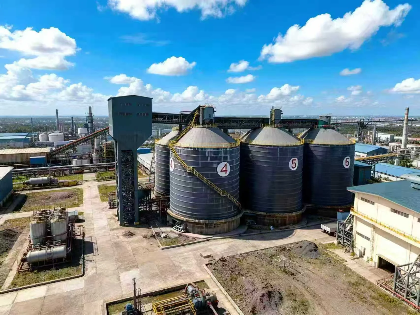
When a tanker truck unloads cement into a silo at rates of 60–120 tonnes per hour, the displaced air carries fine dust that creates a pressure wave. Without adequate venting, internal pressure can spike to 1.5–2 times the design limit. Most spiral steel silos for cement and fly ash are designed to withstand 0.15–0.30 bar positive pressure, but relief valves must activate well before that threshold—typically at 70–80% of design pressure.
We've seen cases where a single blocked vent caused the silo roof to buckle during a 50-tonne delivery. The root cause wasn't structural weakness; it was a relief valve set too high or clogged with hardened cement dust. This is why regular inspection of the valve's sealing surface and spring mechanism is as critical as the initial sizing calculation.
Relief Valve Sizing: Airflow Rate and Pressure Drop Calculations
The key parameter is the required venting capacity, measured in cubic meters per hour (m³/h) at standard conditions. For a typical cement silo receiving 80 tonnes per hour, the displaced air volume is roughly 800–1,200 m³/h, depending on the aeration system and conveying pressure. A properly sized relief valve must handle at least 1.5 times this peak flow to account for surge events.
Calculating Effective Orifice Area
Use the formula A = Q / (C × √ΔP), where A is the required orifice area in cm², Q is the venting flow rate in m³/h, C is the discharge coefficient (typically 0.6–0.8 for poppet-style valves), and ΔP is the allowable pressure differential in bar. For a 0.2 bar design pressure, a single 300 mm diameter valve with a 0.7 coefficient can handle approximately 2,500 m³/h—adequate for most single-compartment silos.
Common Sizing Mistakes in Field Installations
One frequent error is installing a valve based on silo volume alone, ignoring the filling rate. A 500 m³ silo filled at 120 t/h needs a larger valve than the same silo filled at 40 t/h. Another oversight is neglecting the pressure drop across ductwork—every 90-degree bend adds 10–15% resistance. Always verify the valve's certified flow curve against your actual conveying system parameters.
Key Takeaways
- Core Data Point: Relief valves should activate at 70–80% of silo design pressure, with a safety margin of 1.5× peak airflow during filling.
- Best Practice: Size the valve based on actual filling rate (t/h) and conveying air volume, not silo volume alone.
- Risk Alert: Dust accumulation on valve seats can reduce effective capacity by 40% within six months—schedule quarterly cleaning.
Material Compatibility and Valve Configuration for Cement Dust
Cement dust is hygroscopic and abrasive. Standard carbon steel valves with painted surfaces often fail within two years due to corrosion and wear. We recommend stainless steel 304 or 316 for all wetted parts, with PTFE seals to prevent sticking. The valve design should also include a weather hood and a manual test lever—two features that are frequently omitted but essential for reliable operation in outdoor installations.
For silos handling fly ash or blended cements, the valve's spring tension must be adjustable to accommodate different bulk densities. A valve set for Portland cement may not open correctly for lighter fly ash, leading to either premature venting or delayed response. A professional manufacturer can provide calibrated springs for your specific material. For more on accessory selection, see our guide on essential cement silo accessories for peak performance.
Integrating Relief Valves with Structural and Safety Systems
A relief valve is only one component of a comprehensive safety strategy. It must work in concert with pressure sensors, high-level alarms, and dust collection systems. We've observed that silos equipped with both mechanical relief valves and electronic pressure monitoring have a 60% lower incident rate compared to those relying on one system alone. The valve's discharge path should also be directed away from walkways and equipment to prevent dust clouds from accumulating near ignition sources.
During the silo design phase, the roof's structural reinforcement around the valve flange is often overlooked. A 400 mm valve can exert over 5 kN of force during a sudden opening event. The mounting ring must be welded to the roof with stiffeners to distribute this load. For a deeper look at how structural integrity and explosion prevention intersect, read our article on cement silo safety: dust explosion prevention and structural integrity.
Frequently Asked Questions
Q: How do I determine if my existing relief valve is undersized for a new higher-capacity filling system?
A: Measure the actual pressure spike during a peak-rate filling event using a calibrated pressure transducer. If the pressure exceeds 80% of the silo's design limit for more than 10 seconds, the valve is likely undersized. Also calculate the new maximum airflow rate using the formula Q = (conveying air volume + displaced air) × 1.5 safety factor, and compare it to the valve's certified flow capacity at your operating pressure.
Q: Can I install a vacuum relief valve and a pressure relief valve as a combined unit on a cement silo?
A: Yes, combined pressure/vacuum relief valves are common, but they require careful spring selection to handle both positive and negative pressure ranges. For cement silos, vacuum protection is equally critical—a rapid discharge can create -0.05 bar vacuum, which can collapse a spiral silo wall. Ensure the combined valve has separate spring chambers for each function, and that the vacuum setting is at least 20% below the silo's collapse pressure.
Looking for Professional Silo Storage Solutions?
We provide customized design, manufacturing, and installation services for steel silo systems worldwide.
Get Your Free Technical Consultation →